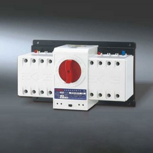
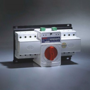
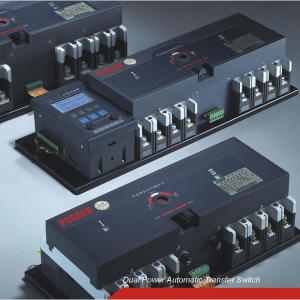
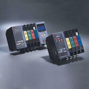
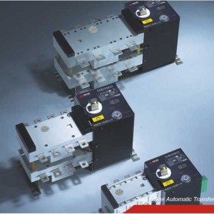
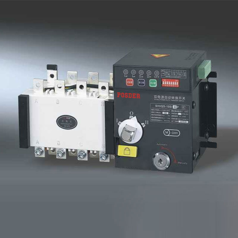
SHIQ5-III Series Double Power Automatic Transfer Switch
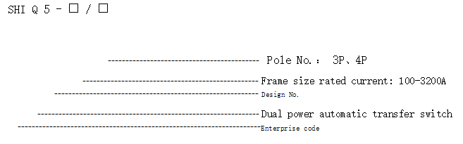
Model and meaning
Performance and features
♦Adopt double row composite contact, horizontal pulling mechanism, micro-machine pre-stored energy and micro electronic control technology, basically realize zero flashover (no arc extinguishing chamber).
♦Adopt reliable mechanical interlock and electrical interlock, the executive component adopts independent load-disconnector switch, safe and reliable use.
♦Adopt current-zero position technology, under emergency situations, it can be forced to zero setting (cut off two power supply at the same time), meet the needs of fire control linkage.
♦The switchover of execution load isolating switch is driven by the single motor, the switchover is stable and reliable, without noise, small impact force.
♦The current only passes through the manipulator d riving motor at the moment when the execution load-disconnector switch is switched on, no need to provide working current in steady operation, significantly save energy.
♦The execution load-disconnector switch is equipped with a mechanical interlock device to ensure that the common and standby power supply work reliably without interference.
♦Own obvious the on-off position indicating and padlock functions, which reliably achieves isolation between the power supply and the load.
♦Good safety performance, high degree of automation, high reliability, its service life is more than 8000 times.
♦Mechanical-electrical integration design, the switch is accurate, flexible and smooth; use international advanced logic control technology; strong anti-interference ability, external interference free.
♦Three kinds of stable work (I-O-II): the main power supply closes, standby power supply opens; the main power supply opens, standby power supply closes; the main power supply and standby power supply both opens.
♦Easy to install, the control circuit adopts the plug-in terminal connection.
♦Four kinds of operating functions: emergency manual operation, electric remote-control operation, emergency disconnection operation in automatic control state and automatic control operation.
Main technical parameters
|
Model Item SHIQ5-100 |
SHIQ5 -160 |
SHIQ5 -250 |
SHIQ5 SHIQ5 -400 -630 |
SHIQ5 -800 |
SHIQ5 SHIQ5
-1250 -1600 |
SHIQ5 SHIQ5
-2500 -3200 |
|||
| Usage category |
AC-33iB |
||||||||
| Ue Rated working voltage |
AC400V |
AC380V |
AC380V |
AC400V |
AC400V |
AC400V |
AC400V |
AC400V | |
| Ui Rated insulation voltage | 690V |
690V |
690V |
690V | 690V |
690V |
690V |
690V | |
| Uimp
Rated impulse withstand voltage |
6kV |
6kV |
6kV |
6kV |
6kV |
6kV |
6kV |
8kV | |
| lew
Rated short-time withstand current |
10kA |
- |
- |
30kA | 30kA |
- |
- |
- |
|
| Service lifetimes) | Mechanical | 4500 |
5000 |
5000 |
3000 | 2000 |
2500 |
2500 |
1500 |
| Electrical | 1500 |
1000 |
1000 |
1000 | 1000 |
500 |
500 |
500 | |
| Pole No. |
3、4 |
||||||||
| Operating cycles(S/times) |
30S |
60S |
|||||||
| Switching time |
0 〜99S |
||||||||
Structural features and functions
The switch controlled by various logic commands that are sent by the control circuit board to manage the motor, which is driven by the motor, the gear box is decelerated to drive the spring to be stored and released in an instant. Thus, the circuit can be connected with the breaking circuit or the circuit to be switched quickly, and the security isolation can be realized through the visible state.
Switch can be realized automatic charge and automatic recovery, automatic charge and non-automatic recovery, fire fighting function (forced to "0"), emergency manual operation: It also has the functions of phase detection protection, overvoltage protection, undervoltage protection and starting with generator (oil machine).
♦ Control type: A is basic type, B is intelligent type
A type is basic type function: loss of voltage (any phase) conversion, return to normal value return; its undervoltage, conversion and delay time can not be set.
♦ Conversion mode
1. Automatic charge and automatic recovery: When the common power supply (I) power off (or phase failure), overvoltage and undervoltage, the switch will automatically switch to the standby power supply (II). And when the common power supply (I) back to normal, the switch automatically return to the common power supply (I).
2. Automatic charge and non-automatic recovery: When the common power supply (I) power off (or phase failure), overvoltage and undervoltage, the switch will automatically switch to the standby power supply (II). And when the common power supply (I) back to normal, the switch remains in the standby power supply (II) and does not automatically return to the common power supply (I).
♦ Protection detection conversion function
1. Detection of common power supply arbitrary phase loss, loss of power protection conversion function.
2. Detection of common power supply arbitrary phase and N voltage: overvoltage 265V, under pressure 170V protection conversion function.
♦Fire-fighting function (forced to "0"): remote control and automatic conversion to "0" to cut off the load power supply, when the switch fire function (forced to 0) must be reset, you must manually press the switch "reset key" to restore to the automatic state.
♦ Starting function of generator (oil machine)
♦ Introduction to function of control and output terminals
(1) SHIQ5-100 Introduction to function of output terminals
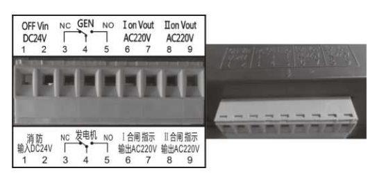
1. OFF Vin DC24V:
① and ② terminals are firefighting function (forced to 0), and the input voltage of DC24V.
2. GEN: Generator (oil machine)
Terminal ③ is the normally closed terminal NC of generator
Terminal ④ is the public terminal COM of generator
Terminal ⑤ is the normally open terminal NO of generator
3. Ion Vout AC220V:
⑥ and ⑦ terminals are common power supply (I) closing instructions, and the output voltage is AC220V.
4. lion Vout AC220V:
⑧ and (9) terminals are standby power supply (II) closing instructions, and the output voltage is AC220V.
(2) SHIQ5-160 – 630/ Introduction to function of output terminals
1. I closing instruction:
① and ② terminals are common power supply (I) closing instruction switch, passive output
2. II closing instruction:
(3) and ④ terminals are standby power supply (II) closing instruction switch, passive output
3. Fire input DC24V:
⑤ and ⑥ terminals are fire-fighting function (forced to "0"), and the input voltage is DC24V.
4. Generator (oil machine)
Terminal ⑦ is the normally closed terminal NC of generator
Terminal ⑧ is the normally open terminal NO of generator
Terminal ⑨ is the public terminal COM of generator
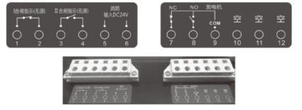
(3) SHIQ5-800 〜3200/ Introduction to function of output terminals
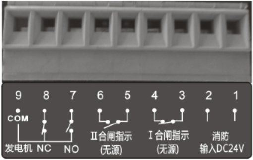
1. Fire input DC24V:
① and ② terminals are fire-fighting function (forced to "0"), and the input voltage is DC24V.
2. I closing instruction:
(3) and ④ terminals are common power supply (I) closing instruction switch, passive output
3. II closing instruction:
⑤ and ⑥ terminals are standby power supply (II) closing instruction switch, passive output
4. Generator (oil machine)
Terminal ⑦ is the normally open terminal NO of generator
Terminal ⑧ is the normally closed terminal NC of generator
Terminal ⑨ is the public terminal COM of generator
5. 1power supply indication:
⑩ and ⑪ terminals are common (I) power supply instructions, and the output voltage is AC220V.
6. II power supply indication:
⑫ and ⑬ terminals are standby (II) power supply instructions, and the output voltage is AC220V.
♦Switch panel buttons and instruction function introduction:
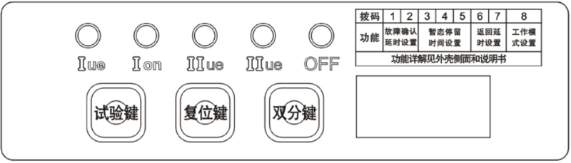
1. Test key: Each time the test key is pressed, the common power supply (I) and the standby power supply (II) can be converted to each other. After the test key is pressed, the double indicator light (OFF) flashes, which means it is the test status.
2. Reset key: Press the reset button to reset the switch to the automatic state, the double indicator light (OFF) does not blink.
3. Double bond: Force the switch to "0".
4. I ue: the common power supply (I) indicating that when the I ue indicator flashes, the common power supply is power failure.
5. II ue: standby power supply (II) indication
6. I on: common power supply (I) closing indication
7. II on: standby power supply (II) closing indication
8. OFF: switch double point "0" position indication
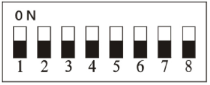
♦ Dial code switch and introduction of related functions
Function detailed as follows:
|
Function explanation |
|||||||||
| Fault confirmation delay setting |
1 |
OFF |
OFF |
ON |
ON |
||||
|
2 |
OFF |
ON |
OFF |
ON |
|||||
|
Duration |
OS |
1S |
3S |
5S |
|||||
| Fault confirmation delay setting |
3 |
OFF |
OFF |
OFF |
OFF |
ON |
ON |
ON |
ON |
|
4 |
OFF |
OFF |
ON |
ON |
OFF |
OFF |
ON |
ON |
|
|
5 |
OFF |
ON |
OFF |
ON |
OFF |
ON |
OFF |
ON |
|
|
Duration |
OS |
3S |
5S |
10S |
20S |
30S |
60S |
90S |
|
| Return delay setting |
6 |
OFF |
OFF |
ON |
ON |
||||
|
7 |
OFF |
ON |
OFF |
ON |
|||||
|
Duration |
OS |
1S |
3S |
5S |
|||||
| Work mode settings |
8 |
OFF |
ON |
||||||
|
Mode |
Automatic charge and automatic recovery |
Automatic charge and non-automatic recovery |
|||||||
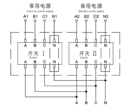
Wiring methods of switch
Main circuit wiring
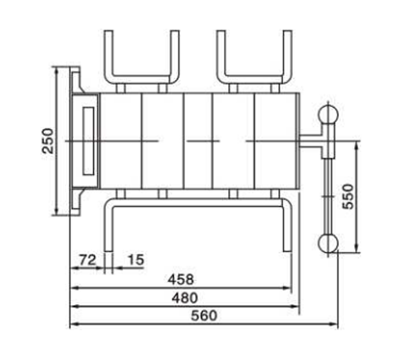
Overall and installation dimension
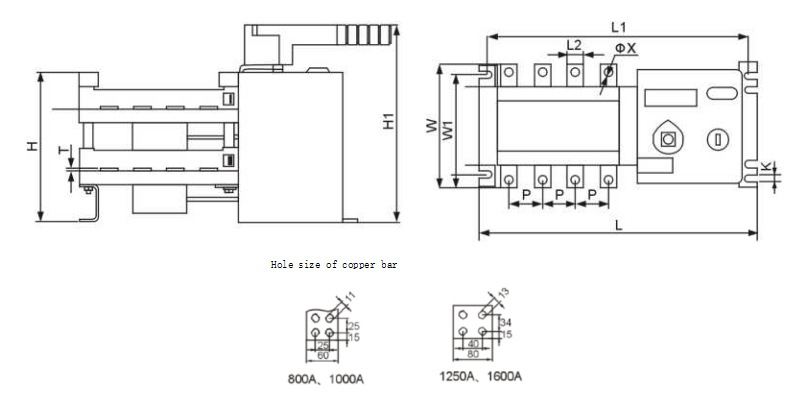
|
Model |
Overall dimension |
Installation dimension |
Copper bar dimension |
||||||||
|
L |
W |
H |
H1 |
L1 |
W1 |
K |
L2 |
T |
OX |
P |
|
| SHIQ5-100/4 | 245 | 112 | 117 |
175 |
225 |
85 |
6.5 |
14 | 2.5 |
6.2 |
30 |
| SHIQ5-160/4 | 298 | 150 |
160 |
225 |
275 |
103 | 7 | 20 | 3.5 |
9 |
36 |
| SHIQ5-250/4 | 363 | 176 |
180 |
240 |
343 |
108 | 7 | 25 | 3.5 | 11 | 50 |
| SHIQ5-400/4 | 435 | 260 |
240 |
320 |
415 |
180 | 9 | 32 | 5 | 11 | 65 |
| SHIQ5-630/4 | 435 | 260 |
240 |
320 |
415 |
180 | 9 | 40 | 6 |
12.2 |
65 |
| SHIQ5-800,1000/4 | 635 | 344 |
300 |
370 |
610 |
220 | 11 | 60 | 8 | 11 | 120 |
| SHIQ5-1250/4 | 635 | 368 |
300 |
370 |
610 |
220 | 11 | 80 | 8 | 13 | 120 |
| SHIQ5-1600/4 | 635 | 368 |
300 |
370 |
610 |
220 | 11 | 80 |
10 |
13 | 120 |
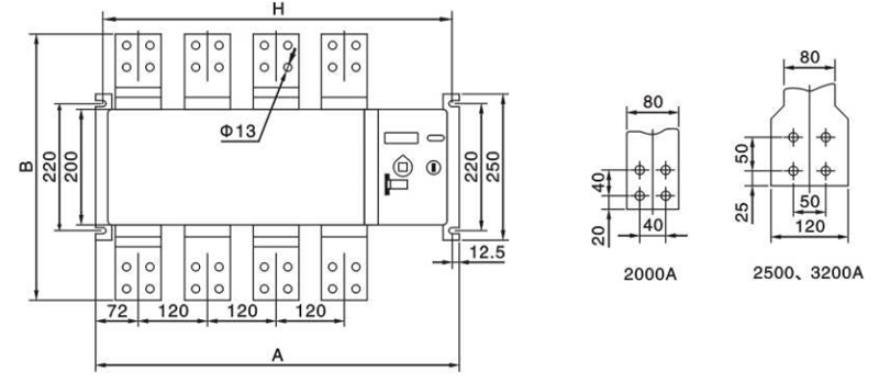
|
Model |
A |
B |
H |
|
SHIQ5-2000/4 |
640 |
460 |
610 |
|
SHIQ5-2500/4 |
640 |
460 |
610 |
|
SHIQ5-3200/4 |
640 |
510 |
610 |
Switch debugging instructions
1. When using the operation handle, the switch is operated repeatedly for three times. The switch should be operated flexibly.
2. Automatic debugging: connecting the corresponding line according to wiring diagram, reopen the electrical lock after confirmation, and then connect the dual power supply, the switch is turned to the "I" file. Then again disconnect the common power supply, the switch is turned to the "II" file; then through the common power supply, the switch should be returned to the "I" file.
3. Forced "0" debugging: in any case, start the forced "0" self locking button, the switch should be turned to the "0" file.
4. Remote control debugging: starting the "I" button, the switch should go to the "I" file; starting the "II" button, the switch should be turned to the "II" file.
5. Detection signal indicator: when the common / standby power is on / off, when the switch "I / II" is on / off, when the electrical / padlock is on / off, all the signal lights should be directed accordingly.
6. After the debugging, please turn off the power first, then the switch is turned to the "0" by handle.
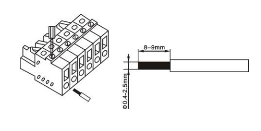
Terminal connection operation instructions
With a small word, as shown in the figure downward force, the wire embedded in the figure