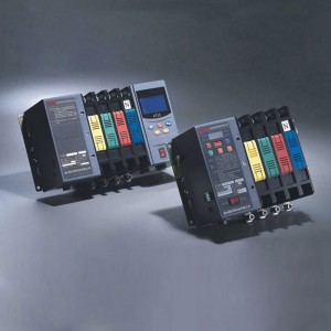
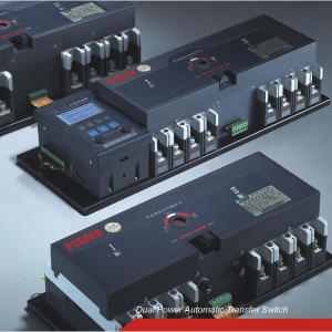
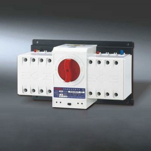
SHIQ5-I/II Series Dual Power Automatic Transfer Switch

Control characteristics
1. Basic type: main-standby power supply, automatic charge and automatic recovery.
♦I type: electric power-electric power(fuIl-automatic);
♦II type: full-automatic, force "0", remote control, with generator.
2. Basic type switch control characteristics:
♦Apply to the main and standby systems of two power sources, automatic charge and automatic recovery;
♦Can be externally connected to expand the function.
Switch control types and corresponding functions
1. 1 type: Automatic
2. II type: Automatic, Forced "0", Remote Control, with Generator
3. Ill type: Switch can be realized automatic charge and automatic recovery, automatic charge and non-automatic recovery, fire fighting function (forced to "0"), emergency manual operation: It also has the functions of phase detection protection, overvoltage protection, undervoltage protection and starting with generator (oil machine).
4. Automatic: Automatic charge and non-automatic recovery: When the common power supply power off (or phase failure), overvoltage and undervoltage, the switch will automatically switch to the standby power supply. And when the common power supply back to normal, the switch remains in the standby power supply and does not automatically return to the common power supply.
5. Forced "0": In case of emergency or equipment overhaul, the forced "0" self-locking button is activated, and the switch is automatically switched to the "0" gear to cut off the two-way power supply.
6. Remote control (remote control): that is, remote operation control, starting the" I" button, the common power supply will be put into operation; starting the "n" button, the standby power supply will be put into operation.
7. With generator (oil machine): When the power supply is cut off (or out of phase), the signal of oil engine start-up will be sent to make the oil engine start automatically. When the power generation is normal, the switch will be automatically converted to the power supply. When the municipal power supply returns to normal, the switch automatically returns to the municipal power supply, and at the same time sends the signal of oil shutdown, which makes the oil machine shut down automatically.
8. Phase-absence detection and protection: Detection and protection of power supply with any phase of power cut.
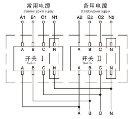
Wiring methods of switch
1. Main circuit wiring
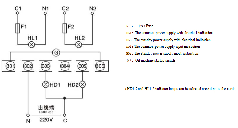
2. SHIQ5-100A/I automatic wiring
3. SHIQ5-100 〜3200A/II automatic, force "0”,remote control wiring
3.1. Automatic wiring (default automatic wiring, 201 and 206 are short connected)
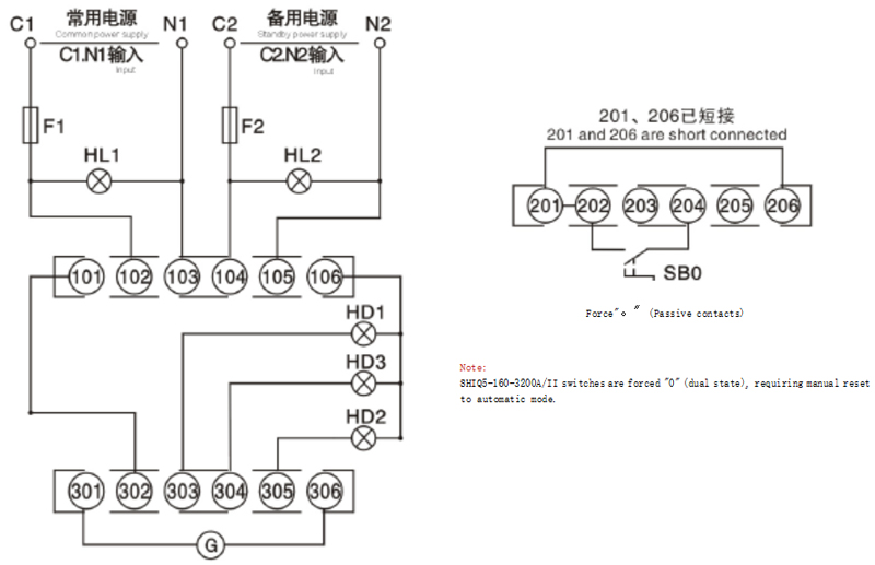
3.2. Automatic, force "0", remote control wiring
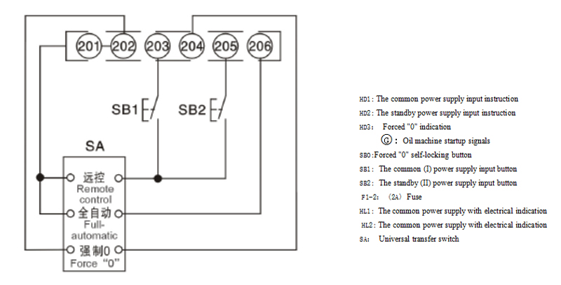
1)HD1-3 and HL1-2 indicator lamps can be selected according to the needs.
2)101 and 106 is the indicator light power supply for switching output, of which 106 is a fire line.
3)The 201 -206 terminal of the II type switch can choose the corresponding function connection according to the need.
4) This product force "0" for (passive contact) input, if DC24V or AC220V is forcing "0", the product needs special customization, please specify.
Wiring instructions
Automatic, force "0" and remote-control wiring, 201-206 terminals need to be connected to the corresponding gear of universal switch according to wiring diagram requirements.
"Remote control" gear: can realize the remote-control switch common power input, standby power input.
"Automatic" gear: The switch operates in fully automatic mode.
"Forced 0" gear: Make the switch force "0" and disconnect the two-power supply.
Note:
1.When the product runs under automatic, forced "0" and remote-control wiring mode, the electric key lock must be opened to "automatic" mode and the hang-up lock cannot be pulled up.
2.When the product runs in remote control mode, it is forbidden to connect 201 to 206.
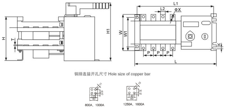
Overall and installation dimension
|
Model |
Overall dimension |
Installation dimension |
Copper bar dimension |
||||||||
|
L |
W |
H |
H1 |
L1 |
W1 | K | L2 | T |
OX |
P |
|
| SHIQ5-100/4 | 245 | 112 | 117 |
175 |
225 |
85 |
6.5 |
14 | 2.5 |
6.2 |
30 |
| SHIQ5-160/4 | 298 | 150 |
160 |
225 |
275 |
103 | 7 | 20 | 3.5 |
9 |
36 |
| SHIQ5-250/4 | 363 | 176 |
180 |
240 |
343 |
108 | 7 | 25 | 3.5 | 11 | 50 |
| SHIQ5-400/4 | 435 | 260 |
240 |
320 |
415 |
180 | 9 | 32 | 5 | 11 |
65 |
| SHIQ5-630/4 | 435 | 260 |
240 |
320 |
415 |
180 | 9 | 40 | 6 |
12.2 |
65 |
| SHIQ5-800,1000/4 | 635 | 344 |
300 |
370 |
610 |
220 |
11 |
60 | 8 | 11 | 120 |
| SHIQ5-1250/4 | 635 | 368 |
300 |
370 |
610 |
220 |
11 |
80 | 8 | 13 | 120 |
| SHIQ5-1600/4 | 635 | 368 |
300 |
370 |
610 |
220 |
11 |
80 |
10 |
13 | 120 |
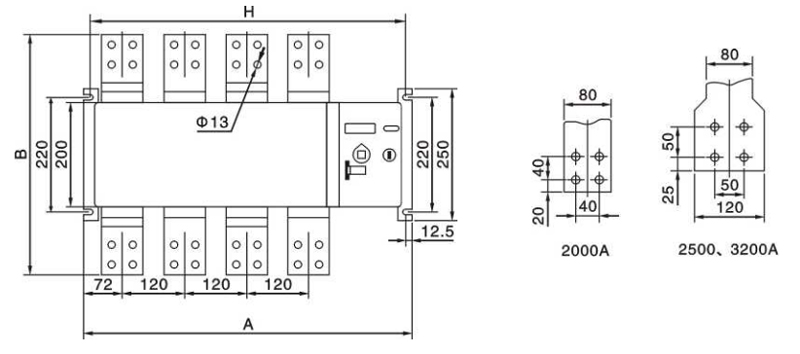
|
Model |
A |
B |
H |
|
SHIQ5-2000/4 |
640 |
460 |
610 |
|
SHIQ5-2500/4 |
640 |
460 |
610 |
|
SHIQ5-3200/4 |
640 |
510 |
610 |
Switch debugging instructions
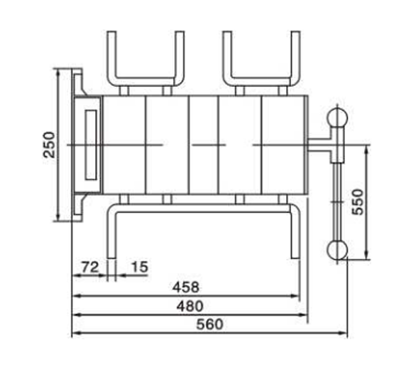
1. When using the operation handle, the switch is operated repeatedly for three times. The switch should be operated flexibly.
2. Automatic debugging: connecting the corresponding line according to wiring diagram, reopen the electrical lock after confirmation, and then connect the dual power supply, the switch is turned to the "I" file. Then again disconnect the common power supply, the switch is turned to the "II" file; then through the common power supply, the switch should be returned to the "I" file.
3. Forced "0" debugging: in any case, start the forced "0" self-locking button, the switch should be turned to the "0" file.
4. Remote control debugging: starting the "I" button, the switch should go to the "I" file; starting the "II" button, the switch should be turned to the "II" file.
5. Detection signal indicator: when the common / standby power is on / off, when the switch "I / II" is on / off, when the electrical / padlock is on / off, all the signal lights should be directed accordingly.
6. After the debugging, please turn off the power first, then the switch is turned to the "0" by handle.
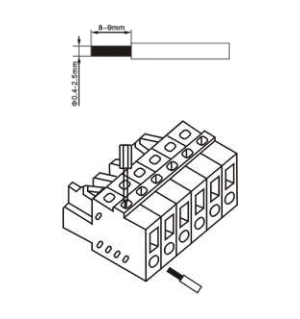
Terminal connection operation instructions
With a small word, as shown in the figure downward force, the wire embedded in the figure