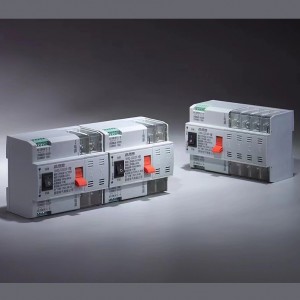
PSDQ-125-V Dual Power Automatic Transfer Switch

GENERAL
Product structure: small size, high current, simple structure, ATS integration
Features: fast switching speed, low failure rate, convenient maintenance, reliable performance
Connection: front connection
Conversion mode: power on the grid, grid generator, auto-charge & auto- recovery
Frame current: 125
Product current: 6, 10 , 16, 20, 32, 40, 50, 63, 80, 100, 125A
Product classification: two sections without double-break position,
Pole No.: 2, 4
Standard: GB/T14048.11
ATSE: PC class
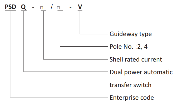
Model and Meaning
Structural Features and Functions
The switch hasthe advantages of small volume, beautiful appearance, reliable conversion, convenientinstallationandmaintenance, and long service life. The switch can realize automatic or manual conversion between common (I) power supply and standby (II) power supply. Automatic conversion: Automatic charge and non -automatic recovery: When the common (I) power supply power off (or phase failure), the switch will automatically switch to the standby (II) powersupply. And when the common (I) power supply back to normal, the switch remains in the standby (II) power supply and does not automatically return to the common (I) power supply. The switch has shortswitching time (millisecond level) in automatic state, which can realize uninterrupted power supply to power grid. Manual conversion: When the switch is in the manual state, it can realize the conversion between the manual common (I) power supply and the standby (II) power supply.
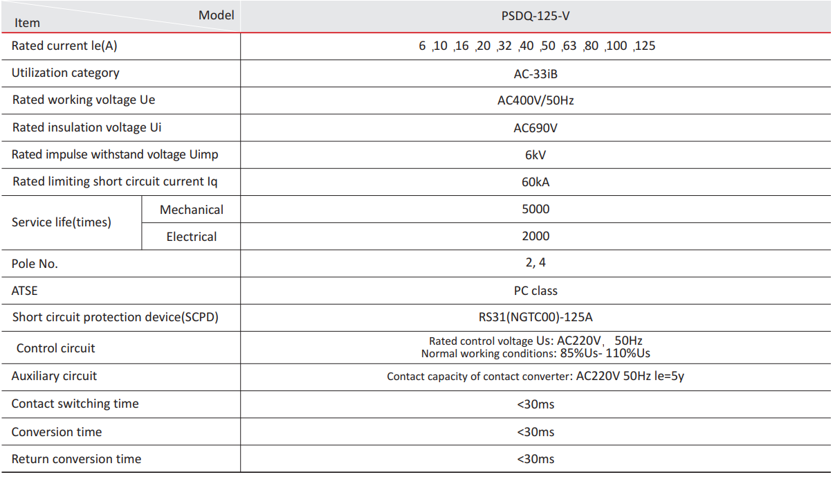
Main Technical Parameters
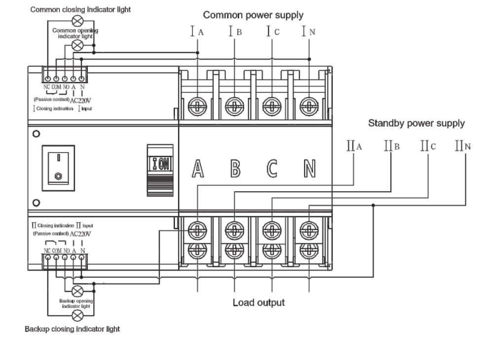
Switch Wiring Diagram
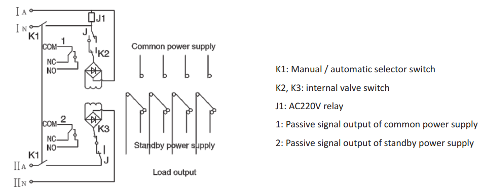
Internal Schematic Diagram of Switch
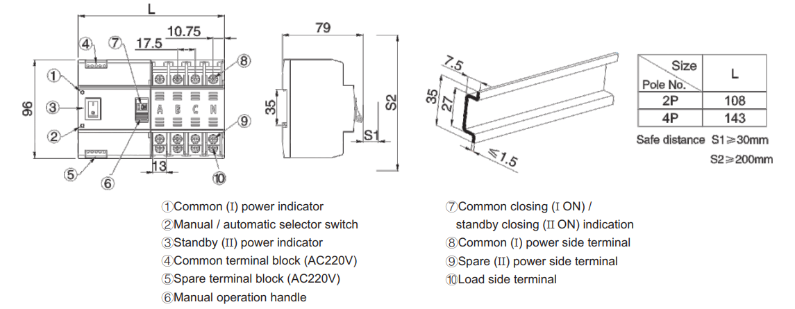
Overall and Installation Dimension
Installation and disassembly method:
1.This switch is installed with 35mm standard guide rail, and the thickness of guide rail sheet metal is less than 1.5 mm.
2. Buckle the lower end of the guide rail groove at the rear of the product into the guide rail first, then push the product upward and press it inward, and install it in place.
3. Disassembly method: Push the product up and then pull it out to complete disassembly.
Use and Maintenance
1. Please check the integrity of the switch before installation.
2. Check the flexibility of the transmission and detectthe load generation and disconnection conditions at each stage of the normal and standby powersupplies.
3. If the installation cannot be carried out according to the correct steps due to wiring and other reasons, please contact us. The safe distances S1 and S2 should not be lower than the mark in the above figure.
4. Maintenance and inspection shall be operated by professionals and all power supplies shall be cut off in advance.
5. Check whether the contact part of each electrical appliance is reliable and compact before, and whether the fuse is in good condition.
6. Detection control voltage: 50Hz/AC220V, and the conductor in the control circuit cannot be too long. The cross-sectional area of copper wire should 2 not be greater than 2.0mm .
7. According to the installation requirements of power distribution system, please provide appropriate circuit breakersto ensure the safety ofstaff and equipment.
8. The switch shall be stored in an environment equivalent to the normal working environment with dust-proof, moisture-proof and collision-proof measures.
9. During the use of the product, general inspection shall be carried out regularly (e.g. every three months of operation), and whether the product is running normally shall be checked once by testing and converting the power supply.