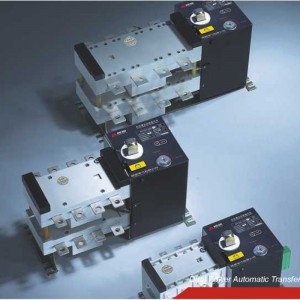
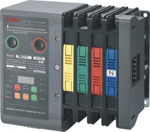
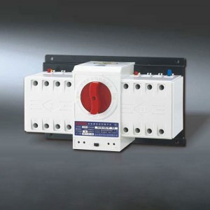
PSDQ5S Dual Power Automatic Transfer Switch (Isolation Type)

GENERAL
Control device: built-in controller
Product structure: small size, high current, simple structure, ATS integration
Features: fast switching speed, low failure rate, convenient maintenance, reliable performance
Connection: front connection Conversion mode: power on the grid, grid generator, auto-charge & auto-recovery
Frame current: 100, 160, 250, 400, 630
Product current: 20, 32, 40, 50, 63, 80, 100, 125, 160, 200, 225, 250, 315, 400, 500, 630A
Product classification: load switch type
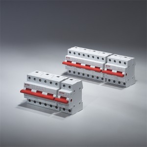
Pole No.: 3, 4
Standard: GB/T14048.11
ATSE: PC class
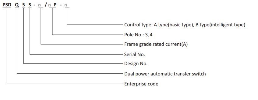
Model and Meaning
Main Technical Parameters
◆ Usage category: AC-33iB
◆ Rated impulse withstand voltage: 6kV
◆ Rated insulation voltage: 690V
◆ Rated short circuit making capacity Icm(peak): 17kA
◆ Rated short-time withstand current Icw: 10kA Electricity time: 30ms
◆ Dielectric strength: 1890V
◆ Mechanical life(times): 6000
Structural Features and Functions
The switch controlled by various logic commands that are sent by the control circuit board to manage the motor, which is driven by the motor, the gear box is decelerated to drive the spring to be stored and released in an instant. Thus, the circuit can be connected with the breaking circuit or the circuit to be switched quickly, and the security isolation can be realized through the visible state.
Switch can be realized automatic charge and automatic recovery, automatic charge and non-automatic recovery, fire fighting function B (forced to "0" ), emergency manual operation: It also hasthe functions of phase detection protection, overvoltage protection, undervoltage protection and starting with generator (oil machine).
◆ Control type: A is basic type, B is intelligent type
A type is basic type function: loss of voltage (any phase) conversion, return to normal value return; its undervoltage, conversion and delay time can not be set.
B type is intelligent type function.
◆ Conversion mode
1. Automatic charge and automatic recovery: When the common power supply (I) power off (or phase failure), overvoltage and undervoltage, the switch will automatically switch to the standby power supply (II). And when the common powersupply (I) back to normal, the switch automatically return to the common power supply (I).
2. Automatic charge and non-automatic recovery: When the common power supply (I) power off (or phase failure), overvoltage and undervoltage, the switch will automatically switch to the standby power supply (II). And when the common power supply (I) back to normal, the switch remainsin the standby power supply (II) and does not automatically return to the common power supply (I).
◆ Protection detection conversion function
1. Detection of common power supply arbitrary phase loss, loss of power protection conversion function.
2. Detection of common power supply arbitrary phase and N voltage: overvoltage 265V, under pressure 170V protection conversion function
◆ Fire-fighting function (forced to "0")
Remote control and automatic conversion to "0" to cut off the load power supply, when the switch fire function (forced to 0) must be reset, you must manually press the switch "reset key" to restore to the automatic state.
◆ Starting function of generator (oil machine)
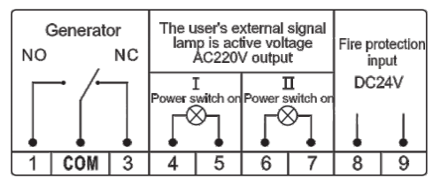
◆ Introduction to function of control and output terminals
1. GEN:Generator (oil machine)
Terminal ① is the normally open terminal NO of generator
Terminal ② is the public terminal COM of generator
Terminal ③ is the normally closed terminal NC of generator
2. I on Vout AC220V:
④ and ⑤ terminals are common power supply (I) closing instructions, and the output voltage is AC220V.
3. II on Vout AC220V:
⑥ and ⑦ terminals are standby power supply (II) closing instructions, and the output voltage is AC220V.
4. OFF Vout DC24V:
⑧ and ⑨ terminals are fire fighting function (forced to 0), and the input voltage of DC24V.
◆ Panel buttons and instruction function introduction:
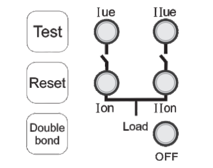
1. Test key: Each time the test key is pressed, the common power supply (I ) and the standby power supply (II ) can be converted to each other. After the test key is pressed, the double indicator light (OFF) flashes, which means it is the test status.
2. Reset key: Press the reset button to reset the switch to the automatic state, the double indicator light (OFF) does not blink.
3. Double bond: Force the switch to "0".
4. I ue: the common power supply(I) indicating that when the I ue indicator flashes, the common power supply is power failure.
5. II ue: standby power supply (II) indication
6. I on: common power supply(I) closing indication
7. II on: standby power supply(II) closing indication
8. OFF: switch double point "0" position indication
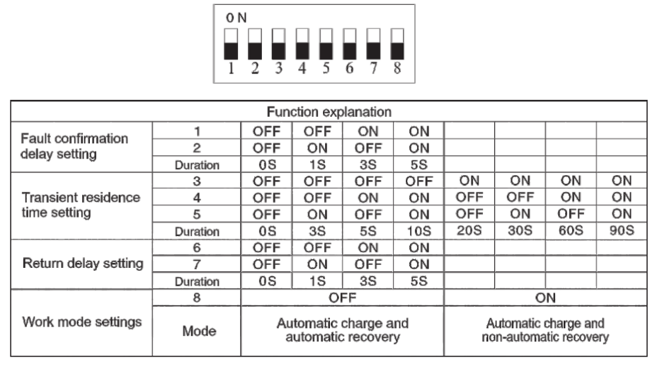
◆ Dial code switch and introduction of related functions
Function detailed as follows:
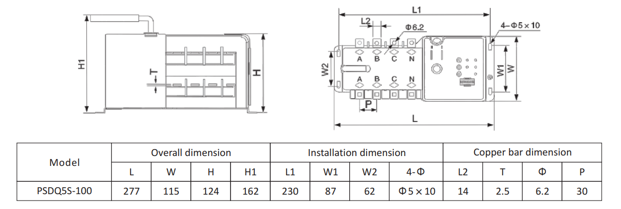
Overall and Installation Dimension